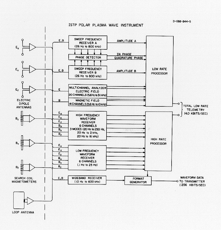
A block diagram of the main electronics package and the associated system of sensors is shown in Figure 4.
Figure 4: A block diagram of the Polar Plasma Wave Instrument, showing the antenna inputs for each of the five receiver systems and the path of the data outputs from the receivers through the digital processing units.
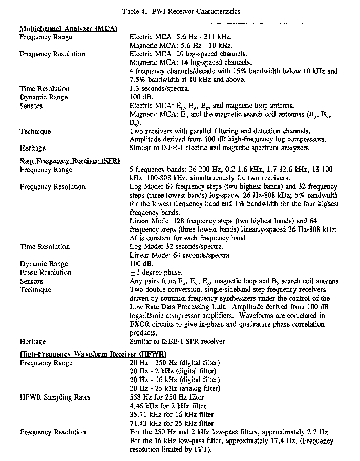
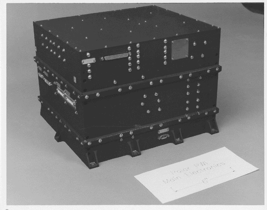
The instrumentation in the main electronics package consists of five receiver systems: a high-time resolution multichannel analyzer (MCA); a narrowband sweep frequency receiver (SFR); a high-frequency waveform receiver (HFWR); a low-frequency waveform receiver (LFWR); and a wideband receiver (WBR). The detailed characteristics of these receiver systems are listed in Table 4a and Table 4b. The receivers can be connected to the electric and magnetic antennas in various combinations by antenna selection switches as listed in Tables 4a and 4b. The sampling of the outputs from the various receiver systems is controlled by two microprocessor-based digital processing units. The Low-Rate Processor (LRP), which uses an 8085 microprocessor, is used to process signals from the SFR and MCA. The High-Rate Processor (HRP), which uses an 8086 microprocessor, is used to perform digital filter operations on data from the WBR. The HRP controls the operation of the WBR and includes a 3.4-megabit waveform capture memory for storage of the HFWR and LFWR waveform data. The LRP and HRP have independent data connections to the spacecraft to prevent complete disruption of the data output due to processor upsets. A photograph of the main electronics package is given in Figure 5.
Figure 5: A photograph of the main PWI electronics package.
The detailed functions of the various receiver systems in the main electronics package are as follows.
The Multichannel Analyzer (MCA) is designed to provide good time resolution with relatively poor frequency resolution. The MCA consists of two spectrum analyzers, one for electric field measurements and the other for magnetic field measurements. The electric MCA consists of 20 channels covering the frequency range from 5.6 Hz to 311 kHz. The magnetic MCA consists of 14 channels covering the frequency range from 5.6 Hz to 10 kHz. These analyzers have relatively coarse frequency resolution (4 frequency channels per decade), but very good time resolution. Above 56 Hz, the averaging time constant is 50 msec. Below 56 Hz, the averaging time constant increases as the inverse of the bandwidth. Below 10 kHz, the channel bandwidths are ±15% of the center frequency of each channel. Above 10 kHz, the bandwidths are ±7.5% of the center frequency of each channel. The center frequencies and bandwidths of the electric MCA and the magnetic MCA channels are identical. The dynamic range of the MCA is approximately 100 decibels (dB). All channels are sampled simultaneously so that the electric-to-magnetic field ratios can be accurately compared. The MCA amplitude output is a 0-5 V DC voltage that is proportional to the logarithm of the field strength. In the normal mode of operation, the analyzer outputs are sampled by the Low-Rate Processor at a rate of approximately one sample every 1.3 seconds. Higher sample rates can be obtained in special modes of operation.
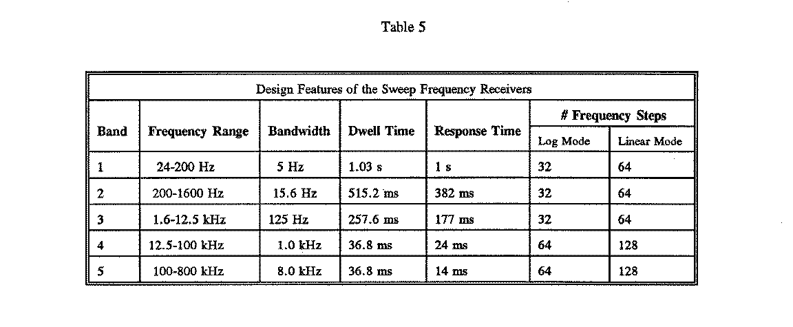
The Sweep Frequency Receiver (SFR) is designed to provide good frequency resolution with relatively poor time resolution. The SFR consists of two single-sideband, phase matched, double-conversion receivers in parallel, with both amplitude and phase-measuring capability. The SFR provides amplitude and phase measurements in five frequency bands from 26 Hz to 808 kHz. Each receiver can be connected to one of four sensors (see Table 4a).
The SFR has two operating modes, the log step mode and the linear step mode. The log step mode has 64 frequency steps in the two highest frequency bands and 32 frequency steps in the three lowest frequency bands. The linear step mode has 128 frequency steps in the two highest frequency bands and 64 frequency steps in the three lowest frequency bands.
In each of the five frequency bands, the frequency channels can be either logarithmically spaced (log step mode) or linearly spaced (linear step mode). In the log step mode, the frequency resolution varies from approximately 8% at 26 Hz to 3% at 800 kHz. The SFR sequentially advances through the frequency spectrum. In the lowest frequency band, 24-200 Hz, a full frequency spectrum can be obtained every 33 seconds in the log mode and every 66 seconds in the linear mode. Because of the wider bandwidths and hence faster response times, the higher frequency bands have faster sweep rates. From 12.5 kHz to 800 kHz, a full frequency spectrum can be obtained every 2.4 seconds in the log mode and every 4.7 seconds in the linear mode. The frequency range, the dwell time on each frequency step, and the number of frequency steps for the five frequency bands are listed in Table 5 for both log and linear modes. Also listed in this table are the response times for SFR bands. The response time is the time for the output of the filter/compressor system to rise from a zero-level output to within 2 dB of the maximum possible output.
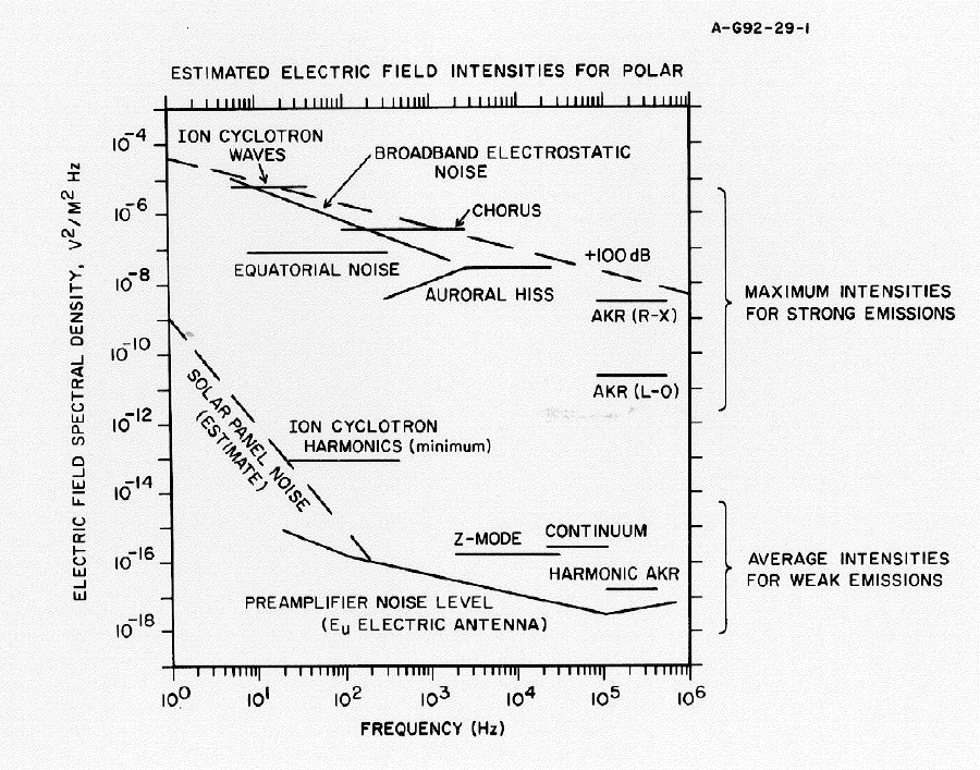
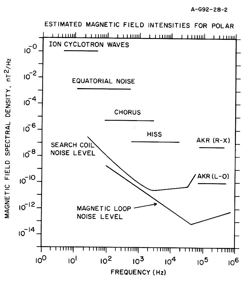
The SFR amplitude output is a 0-5 V DC voltage that is proportional to the logarithm of the signal strength over the 100 dB dynamic range of the instrument. This output is sampled by the Low-Rate Processor. The dynamic range of the instrument and the maximum expected electric and magnetic field spectral densities for a variety of plasma wave phenomena are plotted in Figure 6 and Figure 7.
Figure 6: A plot showing the dynamic range of the PWI and the expected electric field spectral densities for a variety of plasma wave phenomena to be measured by PWI. The estimated spectral densities were derived using plasma wave measurements from the Dynamics Explorer Plasma Wave Instrument. The noise level of the Polar electric antenna was derived from signal sensitivity measurements of the electric antenna preamplifiers and boom buffers, supplied by EFI.
Figure 7: A plot showing the estimated noise levels for the Polar search coil and magnetic loop antennas and the expected magnetic field spectral densities for a variety of plasma wave phenomena to be measured by PWI. The estimated spectral densities were derived using plasma wave measurements from the Dynamics Explorer Plasma Wave Instrument. The noise levels of the Polar magnetic antennas were derived from noise sensitivity tests conducted at the Goddard Space Flight Center Magnetic Test Facility.
The estimated electric and magnetic field spectral densities were derived from plasma wave measurements on the Dynamics Explorer 1 spacecraft.
Phase measurements are obtained by correlating the frequency converted outputs of the two parallel SFR receivers. In-phase and quadrature correlations are obtained. Using ground processing, the in-phase and quadrature measurements can be used to determine the phase between signals on any two selected antennas. The accuracy of the phase measurement is approximately one degree. Phase measurements can be used to determine the wave polarization and propagation direction.
The High-Frequency Waveform Receiver (HFWR) is designed to deliver an instantaneous three-axis snapshot of the electric and magnetic wave fields in one-second waveform segments. These waveforms can be used to determine the wave normal direction and Poynting flux. The HFWR consists of six parallel channels connected to the three orthogonal electric field sensors and the triaxial search coil magnetometer. The relative phase of the input signals is preserved by using phase-matched filters and the same sampling signal for each channel. The output waveforms are digitally sampled using a 12-bit analog-to-digital converter to give a dynamic range of 72 dB. Programmable gain amplifiers with gain steps of 15 dB are used to increase the total dynamic range to 102 dB. Gain updates are initiated by the HFWR software at upper and lower trip points. In the default mode of operation, the upper trip point is set 10 dB below the receiver saturation level. The lower trip point is set 20 dB below the upper trip point. The HFWR gain is updated with each complete waveform capture on all 6 channels. The gain may also be selected manually.
Waveform segments up to one second long are captured in a frequency range from 20 Hz to 25 kHz. In the 16-kHz default mode, a complete waveform is captured on all 6 channels and digitally filtered with an upper frequency cutoff of 16 kHz. The duty cycle is 129 seconds. The phase accuracy of the waveforms is one degree, and the amplitude accuracy is 0.1 dB. On-board digital filtering is used in the High-Rate Processor to synthesize low-pass filters with bandwidths of 250 Hz, 2 kHz, and 16 kHz. During ground processing, FFTs are performed on these waveforms to provide the relative phase and amplitude of signals from the various sensors.
The HFWR can be set to sample any one or a combination of input sensors. The Ev and Ez inputs can be switched to single-ended Ev+ and Ev- input signals, allowing interferometry analysis of the signals from these sensors.
The Low-Frequency Waveform Receiver (LFWR) is designed to provide an extension of the High Frequency Waveform Receiver into the frequency range below 25 Hz. The LFWR consists of six parallel low-pass filters connected to the three orthogonal electric field sensors and to the triaxial search coils. The input signals are band limited to a frequency range from 0.1 to 25 Hz and are sampled by a 12-bit analog-to-digital converter. The six LFWR channels are sampled simultaneously at a rate of 100 samples/second. The dynamic range of the LFWR is approximately 72 dB with fixed gain.
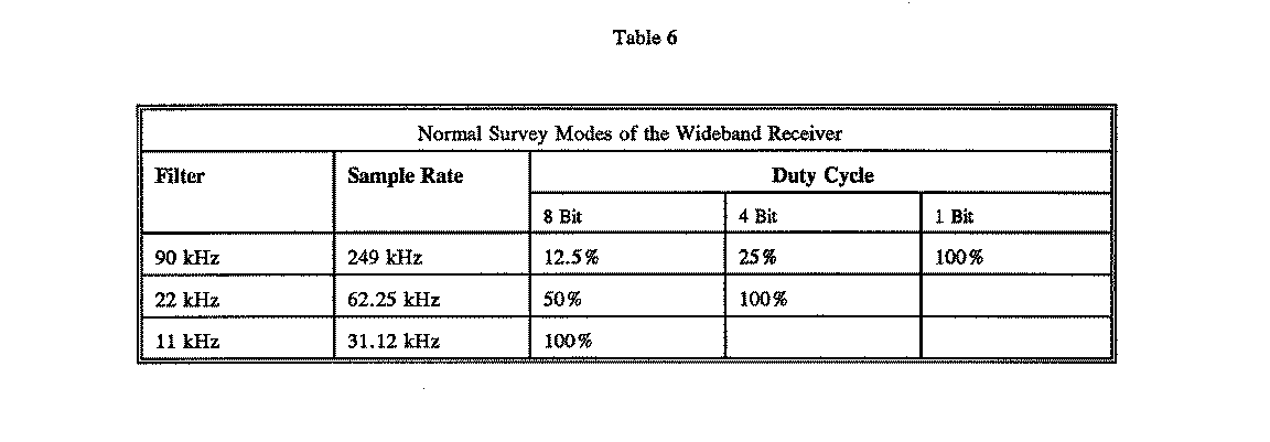
The Wideband Receiver (WBR) is designed to transmit digitized wideband waveform data from a single antenna with very high frequency-time resolution. The WBR has three normal modes of operation with bandwidths of 11, 22, and 90 kHz. In addition, three narrowband filters, 1-3 kHz, 3-6 kHz and 10-16 kHz, can be used to support the analysis of ground VLF transmitter signals. In addition to the bandwidth selection, a frequency conversion scheme can be used to shift the frequency range of the WBR to any one of four frequency ranges with base frequencies of 0, 125, 250, and 500 kHz.
The WBR has three analog-to-digital conversion modes with 1-, 4-, and 8-bit resolution. Each mode adjusts the duty cycle in conjunction with the selected bandwidth to produce a constant output bit rate of 249 kilobits per second (kb/s) to the telemetry system. The default mode of the WBR is the 11- kHz bandwidth at baseband (0 kHz) with 8-bit conversion, which gives a 100% duty cycle. The conversion modes, sample rates and corresponding duty cycles for the three normal mode filters are listed in Table 6.
In the 8-bit mode, the WBR has an instantaneous dynamic range of 48 dB. In the 4-bit mode, the WBR has a dynamic range of 24 dB. Programmable discrete gain amplifiers with a range of 75 dB in 5 dB increments are used in conjunction with the software in the High-Rate Processor to provide an automatic gain control. Gain updates are initiated by the WBR software at upper and lower trip points. In the WBR default mode of operation, the upper trip point is set 10 dB below the receiver saturation level, and the lower trip point is set 12 dB below the upper trip point. In the 11 kHz default mode, the gain state is updated every 0.11 seconds, although this update rate can be modified by the WBR software. The wideband waveform output and the gain state information are formatted into a digital data stream and telemetered to the ground at 256 kb/s.